I have never liked diffraction spikes, they indicate artifacts across the entire field of view, both seen and unseen. This was my attempt to solve the issue: Design 201910056 | IP Australia | Australian Design SearchI designed this for my grandson, who has since died from meningitis along with any interest on my part to finish it. I had registered the design without considering the possibility that it was patentable. Which it was, until I registered it and had it certified. However, the design does have a flaw in it, but I have redesigned it so that it is patentable again. But my interest is still not present. I have attempted to finish it, but also found it had a negative impact on my overall mental health. Not being able to switch off my imagination led to the subject of this post. I have a proof of concept image, which I posted in the EAA group. The image quality is irrelevant and is an effective filter of people who understand what they are seeing and those who don't. Did I mention it is out of focus, which revealed a mistake in a calculation I made to build the device. From failure comes success, etc. With the success of the first light image, I have the protype designed with R.A. & DEC, polar alignment and tracking. The only sticking point now is getting time on the machines at work I need to use to make the parts. The design does not use the bucket method and is not bound by Dawes limit. Also, it is full aperture, unobstructed and does not use any refractive elements. The incident light has a clear path from the primary element to the sensor. Unless you are willing to pay for a patent, I cannot give any more details. But I will be posting the images on this site only and look forward to some clarity. I am not sure how a critique can be given at this point, but that's Heisenberg for you.
|
You cannot like this item. Reason: "ANONYMOUS".
You cannot remove your like from this item.
Editing a post is only allowed within 24 hours after creating it.
You cannot Like this post because the topic is closed.
Copy the URL below to share a direct link to this post.
This post cannot be edited using the classic forums editor.
To edit this post, please enable the "New forums experience" in your settings.
This is the only relevant update: Project available for download.The camera used is only a Hayear HY-500B, but it is sufficient for this project. This is the program used to create the final videos: ImageExtractor06.txtThese are the current results: blue_channel_video.mp4green_channel_video.mp4red_channel_video.mp4The image is an improvement, but I clearly need to work on the rigidity and the centrality of the 1mm aperture. Whether or not it will help me build the final iteration remains to be seen.
|
You cannot like this item. Reason: "ANONYMOUS".
You cannot remove your like from this item.
Editing a post is only allowed within 24 hours after creating it.
You cannot Like this post because the topic is closed.
Copy the URL below to share a direct link to this post.
This post cannot be edited using the classic forums editor.
To edit this post, please enable the "New forums experience" in your settings.
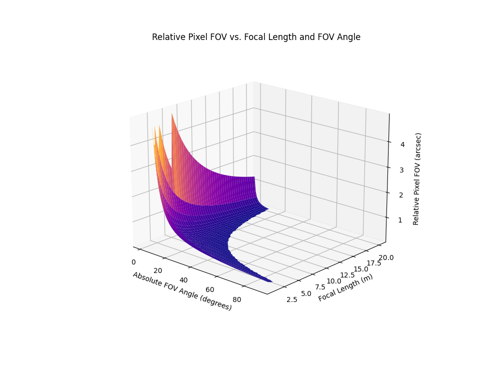
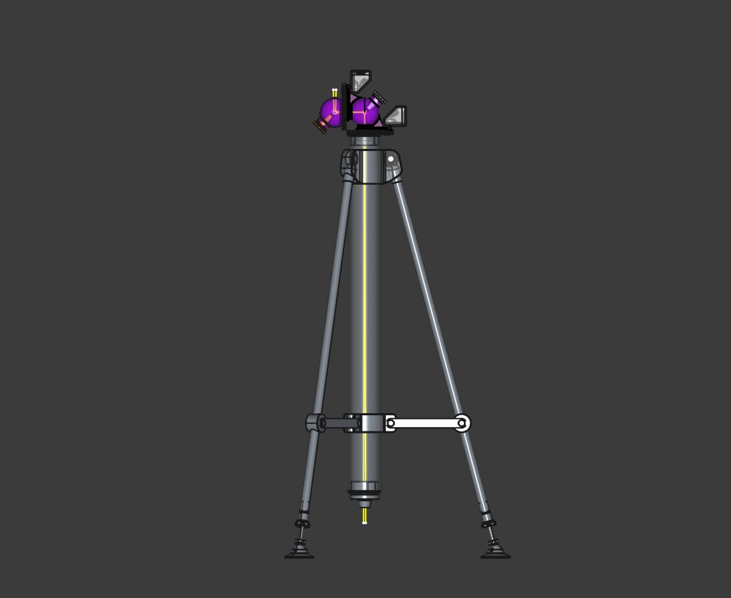
The final design has been decided with which to test the theory and a formula to describe the concept. I don't have the resources to build constantly improving iterations, I have the offcuts at work and a 420mm OD deep groove bearing from the bin. The bearing will form the base of the main stage that is polar aligned to provide tracking. Concept of Relative Pixel FOV: Relative Pixel FOV is calculated based on the pixel size of the camera sensor and the effective focal length of the device. It represents the angle in arcseconds that a single pixel covers on the sky. A smaller relative pixel FOV indicates higher spatial resolution, allowing finer details to be captured in images. Relative Pixel FOV (arcsec/pixel)=2×atan(Pixel Size (microns)/(2×Focal Length (mm))×3600 I have an issue with procrastination and have therefore imposed a deadline of June 30th, 2025. Why, why not! The final device is still based on pinhole theory, just in a considered way. The primary element will be a 1/20th wave, pinhole sized diameter, that converts any light entering the system into incident light with a fixed absolute FOV. The platform anchored to the main bearing contains 20 secondary aluminum reflectors, with each adding 500mm to the total focal length and a proportional reduction in relative pixel FOV. The primary has the option of being coated with different materials to effectively provide an unobstructed form of wavelength filtration without affecting the source light using optical components. The primary targets, once built and calibrated, will be the 20 closest I can see from my location. With M92 being of interest, with the Pop 3 potential. With the device configuration, measuring spectra is just a sensor module swap over. I would apologize for any errors in the formula or theory, but it could be intentional, so I won't.  Stay warm. Paul
|
You cannot like this item. Reason: "ANONYMOUS".
You cannot remove your like from this item.
Editing a post is only allowed within 24 hours after creating it.
You cannot Like this post because the topic is closed.
Copy the URL below to share a direct link to this post.
This post cannot be edited using the classic forums editor.
To edit this post, please enable the "New forums experience" in your settings.
The following are 3D plots made using the formula posted recently to show the relationship between pixel size and relative FOV.  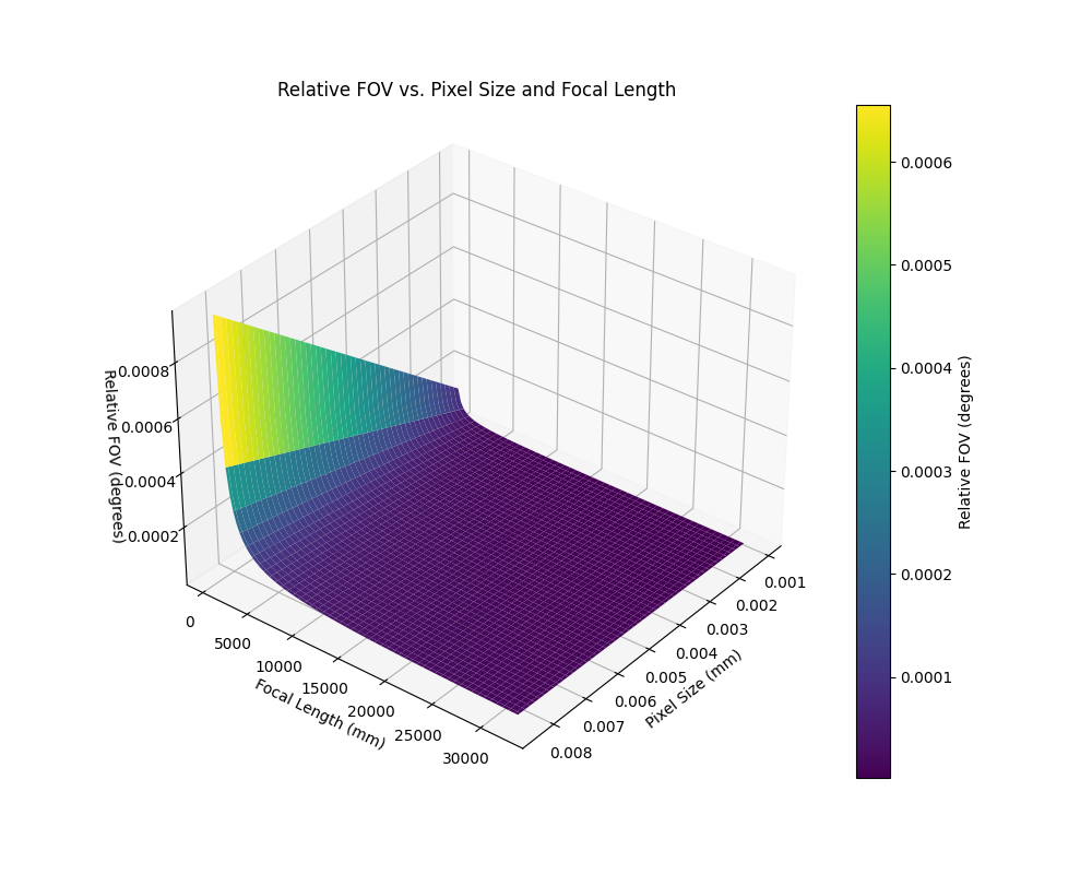 With the device to test this theory. PolarPlatform02.pdfStay warm. Paul
|
You cannot like this item. Reason: "ANONYMOUS".
You cannot remove your like from this item.
Editing a post is only allowed within 24 hours after creating it.
You cannot Like this post because the topic is closed.
Copy the URL below to share a direct link to this post.
This post cannot be edited using the classic forums editor.
To edit this post, please enable the "New forums experience" in your settings.
A funny thing happened the other day, while working out how the hell I was going to build gears accurate enough for the tracking unit, and then I did. As soon as I get some IP protection, I can't really say any more. The result is purely to test the theory and will not be used in the final device. Although, it did remind me of the principle behind projects that stretch the imagination or budget. If the individual or business can afford the loss, the IP harvested from the effort is usually worth it and usually responsible for the blow outs seen historically. I don't like the way the patent system is used to possess another's thought, luckily it was mine, existential crisis averted. The next biggest issue will be the 1/20th surfaces for the other bits. Paul 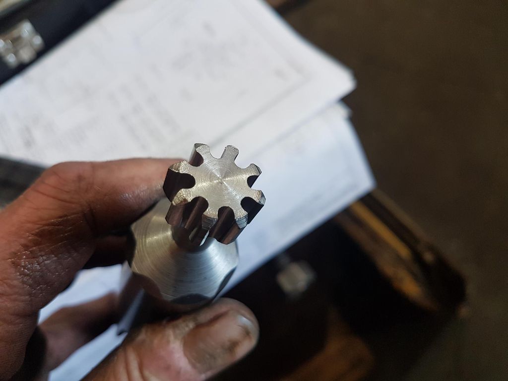 |
You cannot like this item. Reason: "ANONYMOUS".
You cannot remove your like from this item.
Editing a post is only allowed within 24 hours after creating it.
You cannot Like this post because the topic is closed.
Copy the URL below to share a direct link to this post.
This post cannot be edited using the classic forums editor.
To edit this post, please enable the "New forums experience" in your settings.
I have never liked diffraction spikes, they indicate artifacts across the entire field of view, both seen and unseen.
This was my attempt to solve the issue:
Design 201910056 | IP Australia | Australian Design Search
I designed this for my grandson, who has since died from meningitis along with any interest on my part to finish it. I had registered the design without considering the possibility that it was patentable. Which it was, until I registered it and had it certified. However, the design does have a flaw in it, but I have redesigned it so that it is patentable again. But my interest is still not present.
I have attempted to finish it, but also found it had a negative impact on my overall mental health.
Not being able to switch off my imagination led to the subject of this post.
I have a proof of concept image, which I posted in the EAA group. The image quality is irrelevant and is an effective filter of people who understand what they are seeing and those who don't. Did I mention it is out of focus, which revealed a mistake in a calculation I made to build the device. From failure comes success, etc.
With the success of the first light image, I have the protype designed with R.A. & DEC, polar alignment and tracking. The only sticking point now is getting time on the machines at work I need to use to make the parts. The design does not use the bucket method and is not bound by Dawes limit. Also, it is full aperture, unobstructed and does not use any refractive elements. The incident light has a clear path from the primary element to the sensor.
Unless you are willing to pay for a patent, I cannot give any more details.
But I will be posting the images on this site only and look forward to some clarity.
I am not sure how a critique can be given at this point, but that's Heisenberg for you. This seems like a lot of trouble to address something that really isn't a problem; but...ok. The use of a prism will introduce spherochromatism and some field issues. How are you going to handle that? John
|
You cannot like this item. Reason: "ANONYMOUS".
You cannot remove your like from this item.
Editing a post is only allowed within 24 hours after creating it.
You cannot Like this post because the topic is closed.
Copy the URL below to share a direct link to this post.
This post cannot be edited using the classic forums editor.
To edit this post, please enable the "New forums experience" in your settings.
@John HayesThe project that will replace the one registered does not use a prism and should not suffer from spherochromatism, due to all of the surfaces being reflective and planar. Also, it is completely free of any obstructions from the aperture to the image plane, which can only improve image quality. Paul
|
You cannot like this item. Reason: "ANONYMOUS".
You cannot remove your like from this item.
Editing a post is only allowed within 24 hours after creating it.
You cannot Like this post because the topic is closed.
Copy the URL below to share a direct link to this post.
This post cannot be edited using the classic forums editor.
To edit this post, please enable the "New forums experience" in your settings.
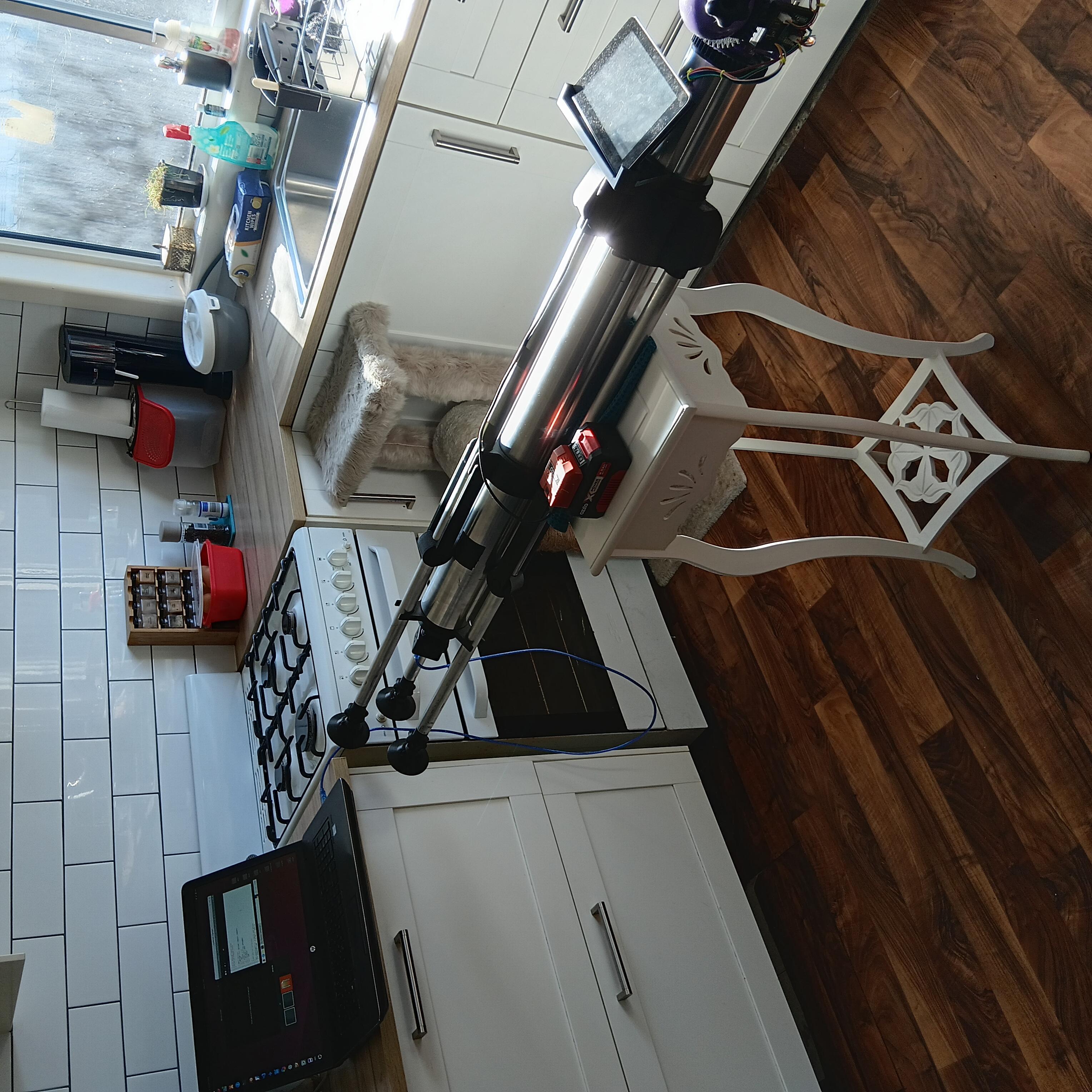
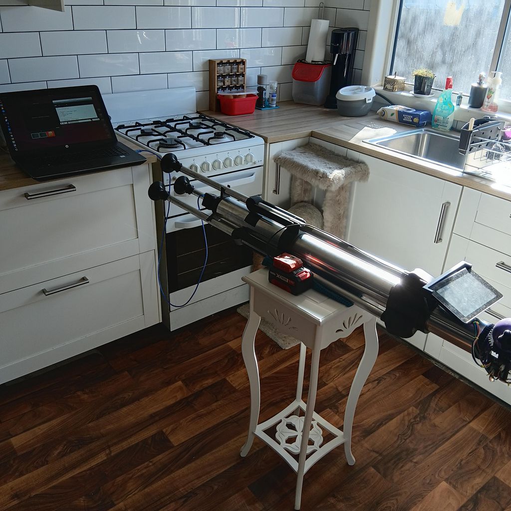  This is the first image from the device shown, which shows the concept works and everything lines up. The horizontal orientation is due to the standing height being outside the rays coming through the window.
|
You cannot like this item. Reason: "ANONYMOUS".
You cannot remove your like from this item.
Editing a post is only allowed within 24 hours after creating it.
You cannot Like this post because the topic is closed.
Copy the URL below to share a direct link to this post.
This post cannot be edited using the classic forums editor.
To edit this post, please enable the "New forums experience" in your settings.
I'm glad to see that you continued your work on this.
You've designed a new diffraction limited design, in an age where almost nobody can say they've made their own optical design to begin with.
I can see merit in the original design in the weight-savings department. The ability to replace a tube, mirror mounts, and spider vanes with a light weight carbon or aluminium spire could save significant amounts of weight, while the image train would be a different issue, I don't think it's too much of a problem to work around. I also don't think this design would need collimation at all if all mirrors are mounted and aligned correctly during manufacturing- maybe primary collimation at most. Secondary obstruction is low, leading to enhanced sharpness, and the speed of the system can potentially be very high. Manufacturing costs potentially reduced too.
My only issues beyond what was stated about the original that I can imagine with this design is that flexture in the spire itself could potentially de-collimate the system via gravitational influence, but I suppose you could create a magnetic ring that can go around the secondary to suspend it at a fixed location, but that may interfere with other electronics… The other being thermal expansion of the optical elements attached to the spire, but you may not experience that with your V2 depending on the design changes you ended up choosing.
I'd love to see an optical diagram or model of the updated version once it's protected- you state that it now has no obstruction- something almost completely unfound in modern reflectors. I too find diffraction spikes annoying, so seeing progress on a novel design that defeats them and obstruction in one package is a pleasant treat.
Keep it up!
|
You cannot like this item. Reason: "ANONYMOUS".
You cannot remove your like from this item.
Editing a post is only allowed within 24 hours after creating it.
You cannot Like this post because the topic is closed.
Copy the URL below to share a direct link to this post.
This post cannot be edited using the classic forums editor.
To edit this post, please enable the "New forums experience" in your settings.
It is difficult to know how much effort to give a project, and up until a couple of days ago, my daughter had no idea till she saw the pinhole sized reflector.
I don't believe any collimation is required, due to using planar only 1st surface reflectors, which eliminate the need. The 3D printed parts are generally with .1mm, so subsequent angles are very close.
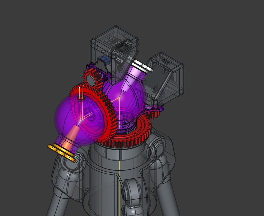
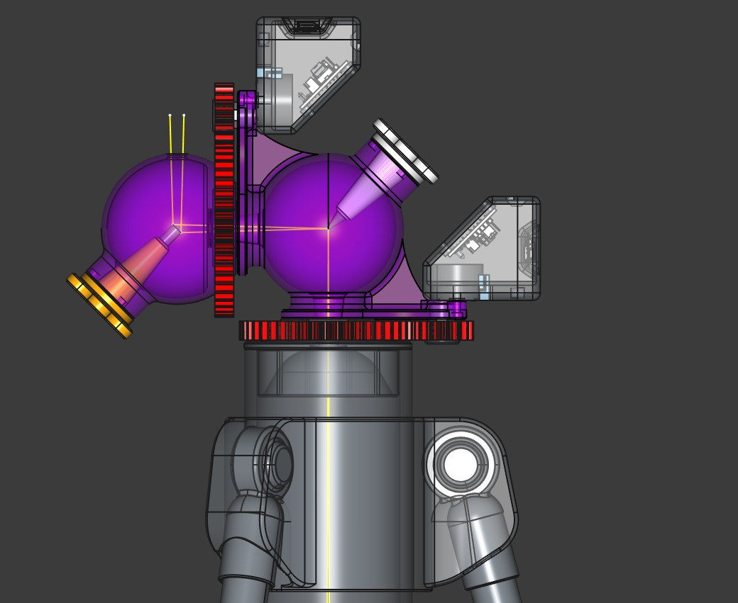
I will upload the optical train shortly.
|
You cannot like this item. Reason: "ANONYMOUS".
You cannot remove your like from this item.
Editing a post is only allowed within 24 hours after creating it.
You cannot Like this post because the topic is closed.
Copy the URL below to share a direct link to this post.
This post cannot be edited using the classic forums editor.
To edit this post, please enable the "New forums experience" in your settings.
After failing to capture anything beside the Sun and struggling to point it using the 3:1 spur gear, I have started printing a 36:1 worm gear alternative, that will be manually operated until the images are improved. Which will require a redesign of the polishing method and jig, etc. The Raspberry Pi only presents a possible barrier for making one, so it could be considered an upgrade, if desired from this point on. 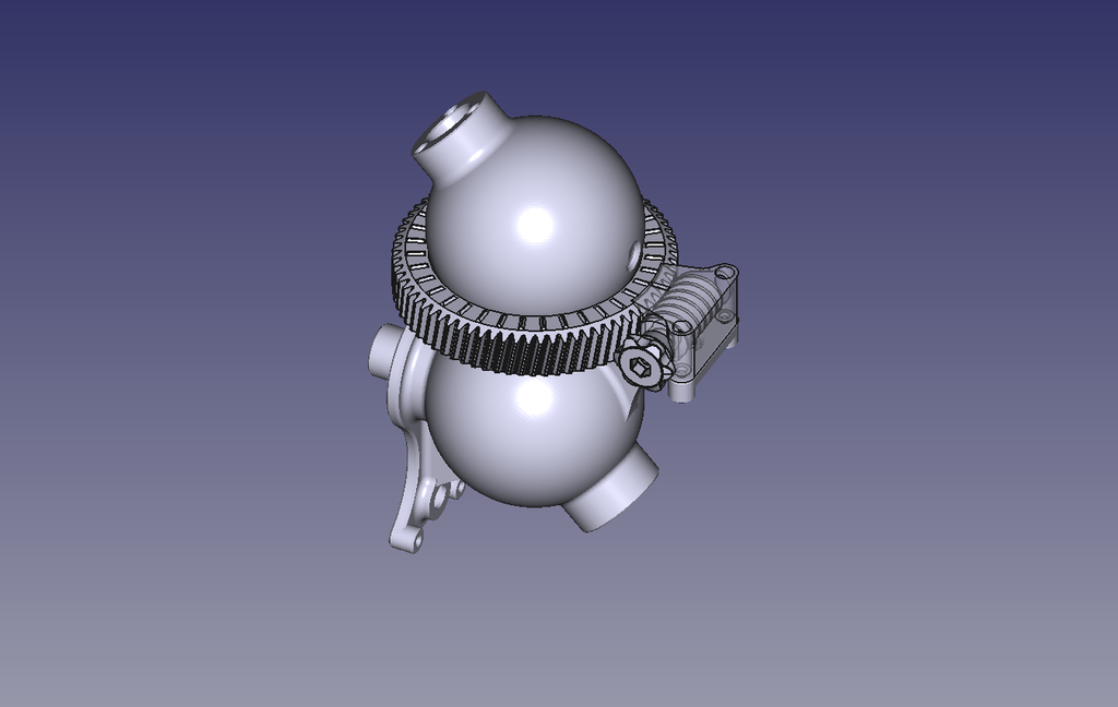 |
You cannot like this item. Reason: "ANONYMOUS".
You cannot remove your like from this item.
Editing a post is only allowed within 24 hours after creating it.
You cannot Like this post because the topic is closed.
Copy the URL below to share a direct link to this post.
This post cannot be edited using the classic forums editor.
To edit this post, please enable the "New forums experience" in your settings.
The primary element was the wrong diameter so the image was out of focus, which means it was behaving as expected, if I had realised the error before even trying.
The only true test will be a globular cluster or galaxy, which will require hardware I don't have, so the image will be some time.
|
You cannot like this item. Reason: "ANONYMOUS".
You cannot remove your like from this item.
Editing a post is only allowed within 24 hours after creating it.
You cannot Like this post because the topic is closed.
Copy the URL below to share a direct link to this post.
This post cannot be edited using the classic forums editor.
To edit this post, please enable the "New forums experience" in your settings.
Interesting take on the second design! Now the question is how to get over the issue of aperture in a design such as this, as it has a very long focal length, with a very small aperture, I'm not sure what the F ratio is, but based on the look of it, it's likely going to struggle with DSO's. I'd recommend you test on the moon first and then go to a star before attempting DSO's, maybe you could make a Mk. III using 2-4 inch mirrors in a superscaled housing down the road? I also imagine the low reduction from the motor to drive to gear setup on this doesn't support tracking very well, as the motor will have to be very high resolution to compensate. Perhaps using a friction drive would support this design better?
|
You cannot like this item. Reason: "ANONYMOUS".
You cannot remove your like from this item.
Editing a post is only allowed within 24 hours after creating it.
You cannot Like this post because the topic is closed.
Copy the URL below to share a direct link to this post.
This post cannot be edited using the classic forums editor.
To edit this post, please enable the "New forums experience" in your settings.
If you don't like diffraction spikes just use an OTA that does not use a spider to support the secondary mirror. Like a Schmidt-Cassegrain.
Bob
|
You cannot like this item. Reason: "ANONYMOUS".
You cannot remove your like from this item.
Editing a post is only allowed within 24 hours after creating it.
You cannot Like this post because the topic is closed.
Copy the URL below to share a direct link to this post.
This post cannot be edited using the classic forums editor.
To edit this post, please enable the "New forums experience" in your settings.
I recognise the struggles it will have just using a pinhole sized primary. The mount I made shown previously has recently passed, after moving the washing rack which was nearby and it toppled over. Legs and Pi support broken, not to worry.
Yesterday I setup a GoFundMe, to obtain a suitable mount and a decent camera.
The true potential lies in how it sees the incident light from interstellar objects. The light from any objects in our solar system are reflected diffusely and the 'bucket scopes' everyone has work fine.
It is a workaround of the Dawes limit. The Mk III design will be a basic OT, one primary element with the ability to adjust the focal length. This will be placed on an equatorial mount with a guide scope to see where it is pointing and a suitable CCD.
I reached out to someone with equipment who I discussed the original registered design with, but I feel he is more concerned for my mental health with the way the design has evolved, which I am not arguing with and haven't heard back.
But the Omega Centauri cluster will show whether or not to continue.
|
You cannot like this item. Reason: "ANONYMOUS".
You cannot remove your like from this item.
Editing a post is only allowed within 24 hours after creating it.
You cannot Like this post because the topic is closed.
Copy the URL below to share a direct link to this post.
This post cannot be edited using the classic forums editor.
To edit this post, please enable the "New forums experience" in your settings.
I recognise the struggles it will have just using a pinhole sized primary. The mount I made shown previously has recently passed, after moving the washing rack which was nearby and it toppled over. Legs and Pi support broken, not to worry.
Yesterday I setup a GoFundMe, to obtain a suitable mount and a decent camera.
The true potential lies in how it sees the incident light from interstellar objects. The light from any objects in our solar system are reflected diffusely and the 'bucket scopes' everyone has work fine.
It is a workaround of the Dawes limit. The Mk III design will be a basic OT, one primary element with the ability to adjust the focal length. This will be placed on an equatorial mount with a guide scope to see where it is pointing and a suitable CCD.
I reached out to someone with equipment who I discussed the original registered design with, but I feel he is more concerned for my mental health with the way the design has evolved, which I am not arguing with and haven't heard back.
But the Omega Centauri cluster will show whether or not to continue. As will a simple daytime test, no tracking needed.
|
You cannot like this item. Reason: "ANONYMOUS".
You cannot remove your like from this item.
Editing a post is only allowed within 24 hours after creating it.
You cannot Like this post because the topic is closed.
Copy the URL below to share a direct link to this post.
This post cannot be edited using the classic forums editor.
To edit this post, please enable the "New forums experience" in your settings.
https://www.youtube.com/watch?v=Ac7G7xOG2AgI think that this YouTube presentation explains this concept a little more clearly. John
|
You cannot like this item. Reason: "ANONYMOUS".
You cannot remove your like from this item.
Editing a post is only allowed within 24 hours after creating it.
You cannot Like this post because the topic is closed.
Copy the URL below to share a direct link to this post.
This post cannot be edited using the classic forums editor.
To edit this post, please enable the "New forums experience" in your settings.
(Spoiler alert!) . . . . . . . I was turboencabulatorolled!  |
You cannot like this item. Reason: "ANONYMOUS".
You cannot remove your like from this item.
Editing a post is only allowed within 24 hours after creating it.
You cannot Like this post because the topic is closed.
Copy the URL below to share a direct link to this post.
This post cannot be edited using the classic forums editor.
To edit this post, please enable the "New forums experience" in your settings.
V:
Interesting take on the second design! Now the question is how to get over the issue of aperture in a design such as this, as it has a very long focal length, with a very small aperture, I'm not sure what the F ratio is, but based on the look of it, it's likely going to struggle with DSO's. I'd recommend you test on the moon first and then go to a star before attempting DSO's, maybe you could make a Mk. III using 2-4 inch mirrors in a superscaled housing down the road? I also imagine the low reduction from the motor to drive to gear setup on this doesn't support tracking very well, as the motor will have to be very high resolution to compensate. Perhaps using a friction drive would support this design better? Application of an f-ratio is invalidated by the lack of aperture to focal point as I am starting at the focal point. The next iteration will be a single primary element OTA, straight to the sensor with a focusing capacity, as opposed to the fixed length currently. I don't like asking for help due to the nature of the project, essentially a 'what if' scenario. But I have started to reach out, with the positive results from testing over the past years. I will redo the Sun and attempt the Moon again and work on procuring an equatorial go-to mount with appropriate cameras for DSOs. The OTA should weigh approximately 1-1.5kg and not require a great deal to point accurately. Based on pinhole theory, a planar surface 4in. diameter would have a focal length of 1.2km +/-, but you could resolve the lunar landing sites. Thank you for the feedback.
|
You cannot like this item. Reason: "ANONYMOUS".
You cannot remove your like from this item.
Editing a post is only allowed within 24 hours after creating it.
You cannot Like this post because the topic is closed.
Copy the URL below to share a direct link to this post.
This post cannot be edited using the classic forums editor.
To edit this post, please enable the "New forums experience" in your settings.
V:
Interesting take on the second design! Now the question is how to get over the issue of aperture in a design such as this, as it has a very long focal length, with a very small aperture, I'm not sure what the F ratio is, but based on the look of it, it's likely going to struggle with DSO's. I'd recommend you test on the moon first and then go to a star before attempting DSO's, maybe you could make a Mk. III using 2-4 inch mirrors in a superscaled housing down the road? I also imagine the low reduction from the motor to drive to gear setup on this doesn't support tracking very well, as the motor will have to be very high resolution to compensate. Perhaps using a friction drive would support this design better?
Application of an f-ratio is invalidated by the lack of aperture to focal point as I am starting at the focal point. The next iteration will be a single primary element OTA, straight to the sensor with a focusing capacity, as opposed to the fixed length currently. I don't like asking for help due to the nature of the project, essentially a 'what if' scenario. But I have started to reach out, with the positive results from testing over the past years.
I will redo the Sun and attempt the Moon again and work on procuring an equatorial go-to mount with appropriate cameras for DSOs. The OTA should weigh approximately 1-1.5kg and not require a great deal to point accurately.
Based on pinhole theory, a planar surface 4in. diameter would have a focal length of 1.2km +/-, but you could resolve the lunar landing sites.
Thank you for the feedback.
I see how that works, very cool!
|
You cannot like this item. Reason: "ANONYMOUS".
You cannot remove your like from this item.
Editing a post is only allowed within 24 hours after creating it.
You cannot Like this post because the topic is closed.
Copy the URL below to share a direct link to this post.
This post cannot be edited using the classic forums editor.
To edit this post, please enable the "New forums experience" in your settings.
If you don't like diffraction spikes just use an OTA that does not use a spider to support the secondary mirror. Like a Schmidt-Cassegrain.
Bob You could easily go that path, but sidestepping innovation and experimentation on the basis of viewing a problem as non-existant or offering existing alternatives that are seemingly perfect as they can be is counterproductive to the technological expansion of the human race. Lets just see how it plays out and save judgement for later once all is said and done. Who knows what this could lead to; I say keep going. MO64 stated that a 4" planar surface pinhole with a ~1.2KM focal length could resolve extraordinary detail, and in that I see a next-generation space telescope for direct exoplanet observation. An Aragoscope of incredible size could also work for incredibly high resolution, but these are purely theoretical at this point.
|
You cannot like this item. Reason: "ANONYMOUS".
You cannot remove your like from this item.
Editing a post is only allowed within 24 hours after creating it.
You cannot Like this post because the topic is closed.
Copy the URL below to share a direct link to this post.
This post cannot be edited using the classic forums editor.
To edit this post, please enable the "New forums experience" in your settings.
V:
You could easily go that path, but sidestepping innovation and experimentation on the basis of viewing a problem as non-existant or offering existing alternatives that are seemingly perfect as they can be is counterproductive to the technological expansion of the human race. Lets just see how it plays out and save judgement for later once all is said and done.
Who knows what this could lead to; I say keep going.
MO64 stated that a 4" planar surface pinhole with a ~1.2KM focal length could resolve extraordinary detail, and in that I see a next-generation space telescope for direct exoplanet observation. An Aragoscope of incredible size could also work for incredibly high resolution, but these are purely theoretical at this point. I hate to burst your bubble but ignoring physics is also "counterproductive to technological expansion of the human race." There is simply nothing innovative about a pinhole camera. They were invented in 1856. A pinhole camera has no formal focal length, they do not have "incredibly high resolution", and they are remarkably light inefficient. Because they operate at a very slow effective focal ratio (radiometrically), they require very long exposures--even for bright objects. A 4" diffraction limited aperture in the far field will have an optical resolution of 2.7" just like any other 4" telescope. That's just how the diffraction of light works. If you go study some diffraction theory, you'll quickly learn that a lens has the property of creating the far-field in the focal plane. That's why 4" telescopes don't need to be 1.2 km long. Pinhole cameras are fun to play around with but you almost certainly are not going to replace James Webb--or any conventional telescope, large or small, with a pinhole camera. John
|
You cannot like this item. Reason: "ANONYMOUS".
You cannot remove your like from this item.
Editing a post is only allowed within 24 hours after creating it.
You cannot Like this post because the topic is closed.
Copy the URL below to share a direct link to this post.
This post cannot be edited using the classic forums editor.
To edit this post, please enable the "New forums experience" in your settings.