First off, your Edge 11 will produce pinpoint stars--and you aren't even close. Second, the back focus distance affects primarily the field performance so that isn't your number-one problem. The correct back focus position for your scope is measured from the rear of the baffle nut to the focus position. It is not measured to the reducer! If you are using the reducer, it's measured from the rear of the reducer to the focus position. But don't start there! Remove the reducer, properly space your sensor, and first make sure that you can achieve sharp focus. I see two primary problems with your data: 1) The sensor is not properly focused, and 2) you've got guiding errors. Since you are using a motorized focuser, are you properly compensating for backlash? Once you have a B-mask, run your autofocus routine and then check it against the B-mask. Getting the sensor focused is the number one thing to do. Then you can work on figuring out where your guiding errors are coming from.
John
|
You cannot like this item. Reason: "ANONYMOUS".
You cannot remove your like from this item.
Editing a post is only allowed within 24 hours after creating it.
You cannot Like this post because the topic is closed.
Copy the URL below to share a direct link to this post.
This post cannot be edited using the classic forums editor.
To edit this post, please enable the "New forums experience" in your settings.
@John Hayes Thanks so much for your feedback. Would love your further input on these: 1. The back-focus distance with or without the reducer is supposed to be 146.05mm. Without the reducer (f/10), it's from the rear of the baffle lock nut to the camera sensor. With the reducer (f/7), it's from the end of the threads to the camera sensor. Is that assumption incorrect? That's exactly what I did, and I am not able to achieve sharp focus when the camera sensor is at 146.05mm from either the baffle lock nut (without the reducer) or the end of the threads of the reducer (with the reducer). 2. My guiding could be better indeed. I have a CGX-L mount and I am guiding with PhD2, and I've made some tweaks to it where I am averaging around 0.5-0.7" of total error on average. I can hopefully can get that to steadily under 0.5 with more effort. 3. The motorized focuser that I have, the Pegasus Prodigy, is supposed to be backlash-free. I get spot on V-curves and the focus position matches the B-mask, so I am unsure what more I can do there. Thanks again for your input!
|
You cannot like this item. Reason: "ANONYMOUS".
You cannot remove your like from this item.
Editing a post is only allowed within 24 hours after creating it.
You cannot Like this post because the topic is closed.
Copy the URL below to share a direct link to this post.
This post cannot be edited using the classic forums editor.
To edit this post, please enable the "New forums experience" in your settings.
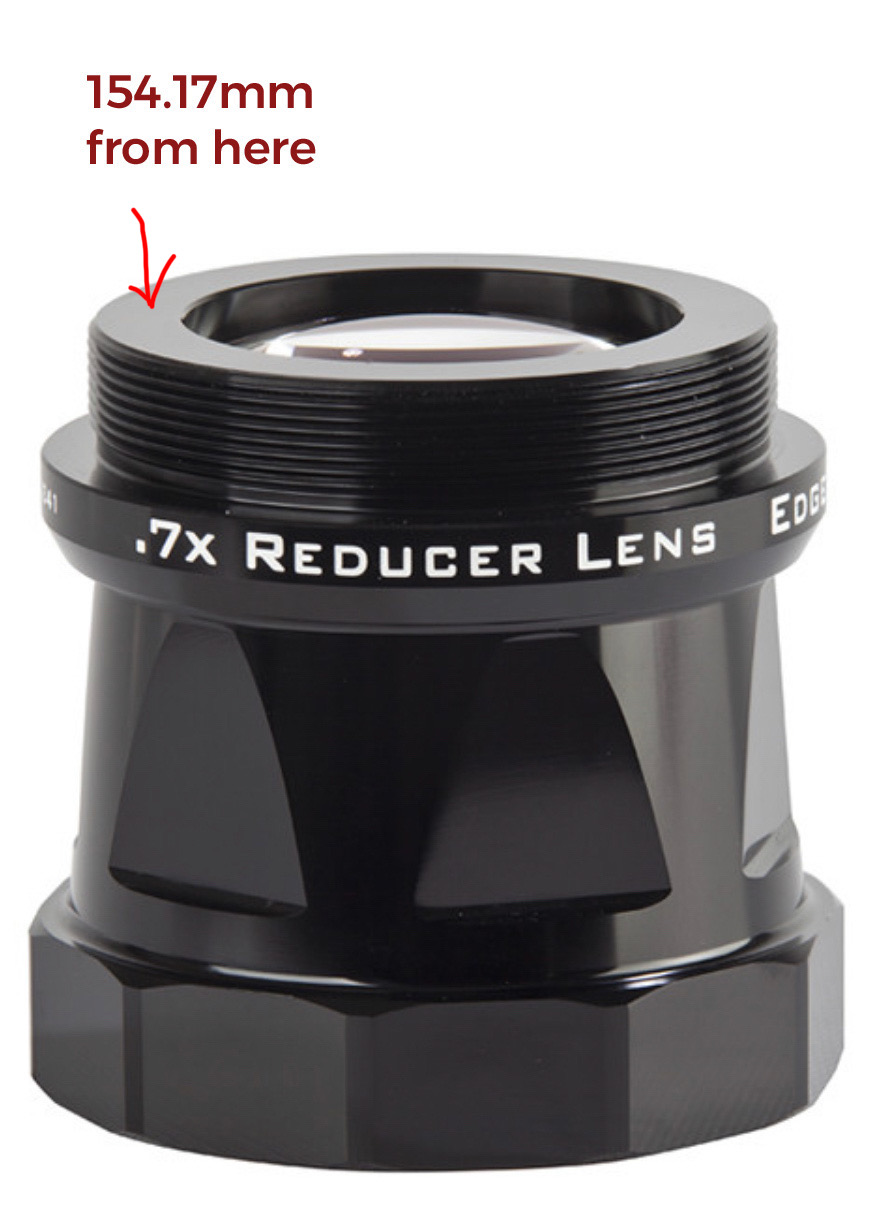
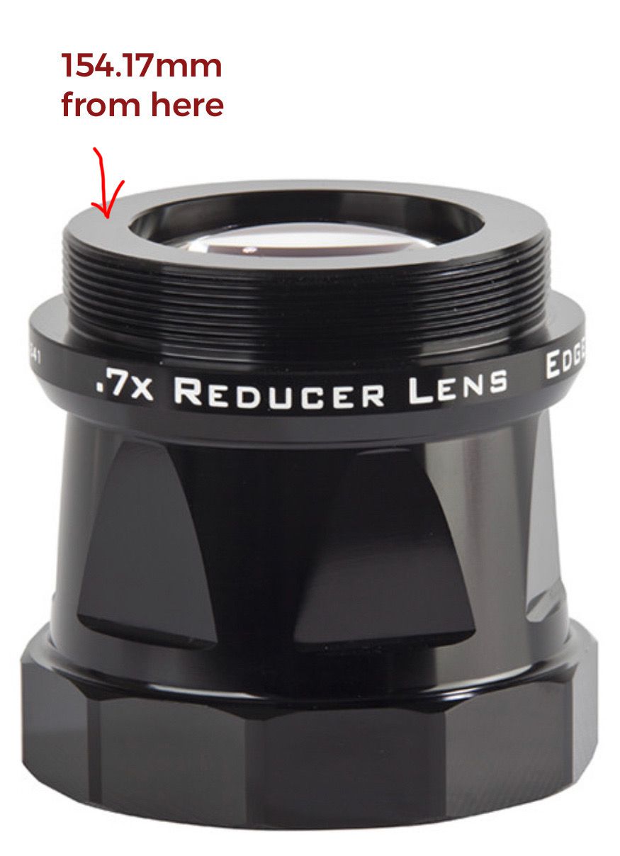
@Michael Legary I am achieving focus at 154.17mm from the end of the 0.7x Reducer (at the end of the threads), not 146.05 which it should be.
 WELL THEN. That is a really interesting issue, and I can only think of one thing causing it, lenses in the Edge HD system undercorrecting, forcing you to have to push backspacing to the limits.
|
You cannot like this item. Reason: "ANONYMOUS".
You cannot remove your like from this item.
Editing a post is only allowed within 24 hours after creating it.
You cannot Like this post because the topic is closed.
Copy the URL below to share a direct link to this post.
This post cannot be edited using the classic forums editor.
To edit this post, please enable the "New forums experience" in your settings.
Thanks for the input @Michael Legary , that would make sense. Let’s see what Celestron comes back with.
|
You cannot like this item. Reason: "ANONYMOUS".
You cannot remove your like from this item.
Editing a post is only allowed within 24 hours after creating it.
You cannot Like this post because the topic is closed.
Copy the URL below to share a direct link to this post.
This post cannot be edited using the classic forums editor.
To edit this post, please enable the "New forums experience" in your settings.
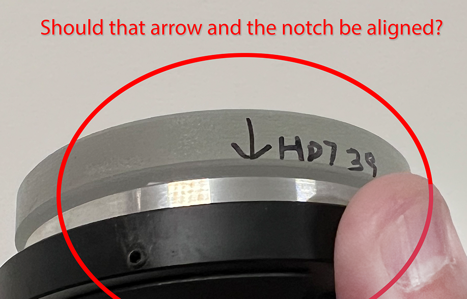
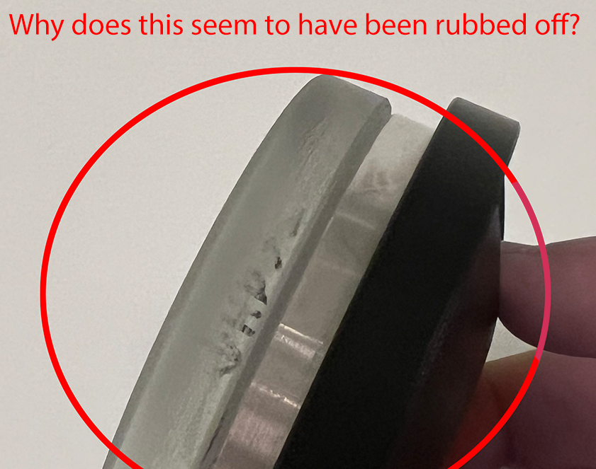
Grasping at straws while awaiting Celestron to get back. I noticed a couple of interesting things with the secondary mirror, and would love input from those who have an EdgeHD. In my case, there is a marking with an arrow, and it’s off from the alignment notch:  And furthermore, there seems to be a previous marking that’s been rubbed off:  I’m wondering if other people with EdgeHD scopes have similar things on their secondary, and if I am just overthinking this.
|
You cannot like this item. Reason: "ANONYMOUS".
You cannot remove your like from this item.
Editing a post is only allowed within 24 hours after creating it.
You cannot Like this post because the topic is closed.
Copy the URL below to share a direct link to this post.
This post cannot be edited using the classic forums editor.
To edit this post, please enable the "New forums experience" in your settings.
Grasping at straws while awaiting for Celestron to get back. I noticed a couple of interesting things with the secondary mirror, and would love input from those who have an EdgeHD.
In my case, there is a marking with an arrow, and it’s off from the alignment notch:
And furthermore, there seems to be a previous marking that’s been rubbed off:
I’m wondering if other people with EdgeHD scopes have similar things on their secondary, and if I am just overthinking this. Astute observation, yes those notches and that mark need to be aligned. They are indexes that provide optimal positions for correcting the field of view. It *could* be worthwhile to move the rubbed index to the notch, and test, then move the original to the index and try again to see if any correction is made. But do this at your own risk.
|
You cannot like this item. Reason: "ANONYMOUS".
You cannot remove your like from this item.
Editing a post is only allowed within 24 hours after creating it.
You cannot Like this post because the topic is closed.
Copy the URL below to share a direct link to this post.
This post cannot be edited using the classic forums editor.
To edit this post, please enable the "New forums experience" in your settings.
Thank you for the prompt input @Michael Legary. Since I have cloudy skies here the next 8-10 days, I will wait for Celestron's reply. This is a brand new scope less than three months old, so I hope they can fix this without me trying to self-service it.
|
You cannot like this item. Reason: "ANONYMOUS".
You cannot remove your like from this item.
Editing a post is only allowed within 24 hours after creating it.
You cannot Like this post because the topic is closed.
Copy the URL below to share a direct link to this post.
This post cannot be edited using the classic forums editor.
To edit this post, please enable the "New forums experience" in your settings.
@John Hayes Thanks so much for your feedback. Would love your further input on these:
1. The back-focus distance with or without the reducer is supposed to be 146.05mm. Without the reducer (f/10), it's from the rear of the baffle lock nut to the camera sensor. With the reducer (f/7), it's from the end of the threads to the camera sensor. Is that assumption incorrect? That's exactly what I did, and I am not able to achieve sharp focus when the camera sensor is at 146.05mm from either the baffle lock nut (without the reducer) or the end of the threads of the reducer (with the reducer).
2. My guiding could be better indeed. I have a CGX-L mount and I am guiding with PhD2, and I've made some tweaks to it where I am averaging around 0.5-0.7" of total error on average. I can hopefully can get that to steadily under 0.5 with more effort.
3. The motorized focuser that I have, the Pegasus Prodigy, is supposed to be backlash-free. I get spot on V-curves and the focus position matches the B-mask, so I am unsure what more I can do there.
Thanks again for your input! 1) Yes. 2) With an Edge11, you want to reduce the errors to be below about 0.3" rms on a night with good seeing. Your target should be 0.25" rms or better for the total error (i.e. with both axis). You'll only get there on a night with good seeing. 3) Ok...that sounds right but make sure that you know how to correctly interpret the B-mask pattern. You need to zoom way in and examine the pattern up close. Try to get it better than 1/10 wave. The diagram below shows a calculated diffraction pattern for perfect and +1/8 wave error. 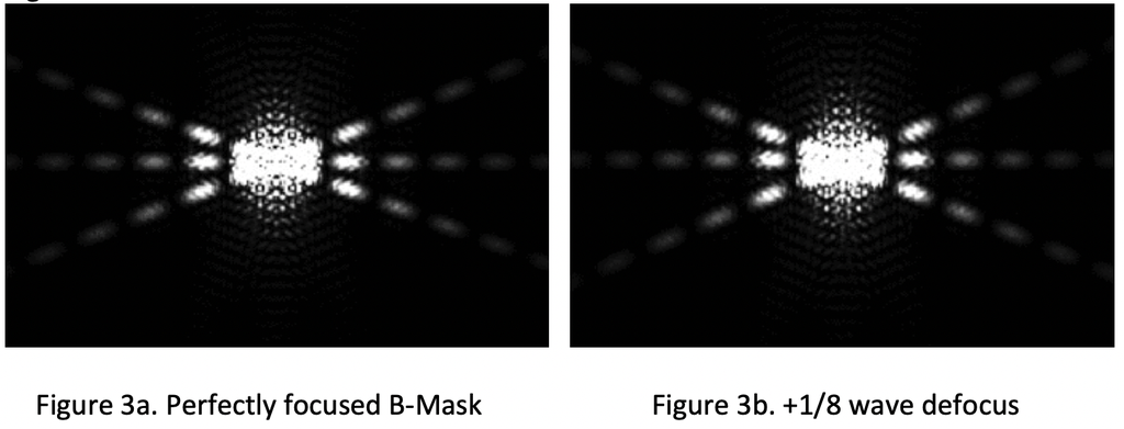 John
|
You cannot like this item. Reason: "ANONYMOUS".
You cannot remove your like from this item.
Editing a post is only allowed within 24 hours after creating it.
You cannot Like this post because the topic is closed.
Copy the URL below to share a direct link to this post.
This post cannot be edited using the classic forums editor.
To edit this post, please enable the "New forums experience" in your settings.
Grasping at straws while awaiting Celestron to get back. I noticed a couple of interesting things with the secondary mirror, and would love input from those who have an EdgeHD.
In my case, there is a marking with an arrow, and it’s off from the alignment notch:
And furthermore, there seems to be a previous marking that’s been rubbed off:
I’m wondering if other people with EdgeHD scopes have similar things on their secondary, and if I am just overthinking this. The clock angle mark that Celestron puts on the secondary is probably not very accurate. They don't have a very good way to accurately align clock angles at the factory so those marks may or may not show the best orientation. The only way to figure out the best orientation is to accurately measure the wavefront and that's not an easy job. There's a rule that you should commit to memory about this stuff and it goes like this: IF IT AN'T BROKE, DON'T FIX IT. Do you have solid evidence that your scope is showing more on-axis astigmatic errors than it should? If you don't, then leave it alone. This is something that once you get everything else working perfectly you might want to carefully check out, but again, you need a much more advanced test to sort this out. An interferometer or SkyWave would be the best ways to go about getting this dialed it but this is not a trivial thing to sort out and it is pretty time consuming. You can read what it takes using a high-end interferometer to align the corrector plate+secondary assembly here: https://www.cloudynights.com/topic/576028-post-script-improving-the-wavefront-quality-of-the-c14-edge/. John
|
You cannot like this item. Reason: "ANONYMOUS".
You cannot remove your like from this item.
Editing a post is only allowed within 24 hours after creating it.
You cannot Like this post because the topic is closed.
Copy the URL below to share a direct link to this post.
This post cannot be edited using the classic forums editor.
To edit this post, please enable the "New forums experience" in your settings.
John Hayes:
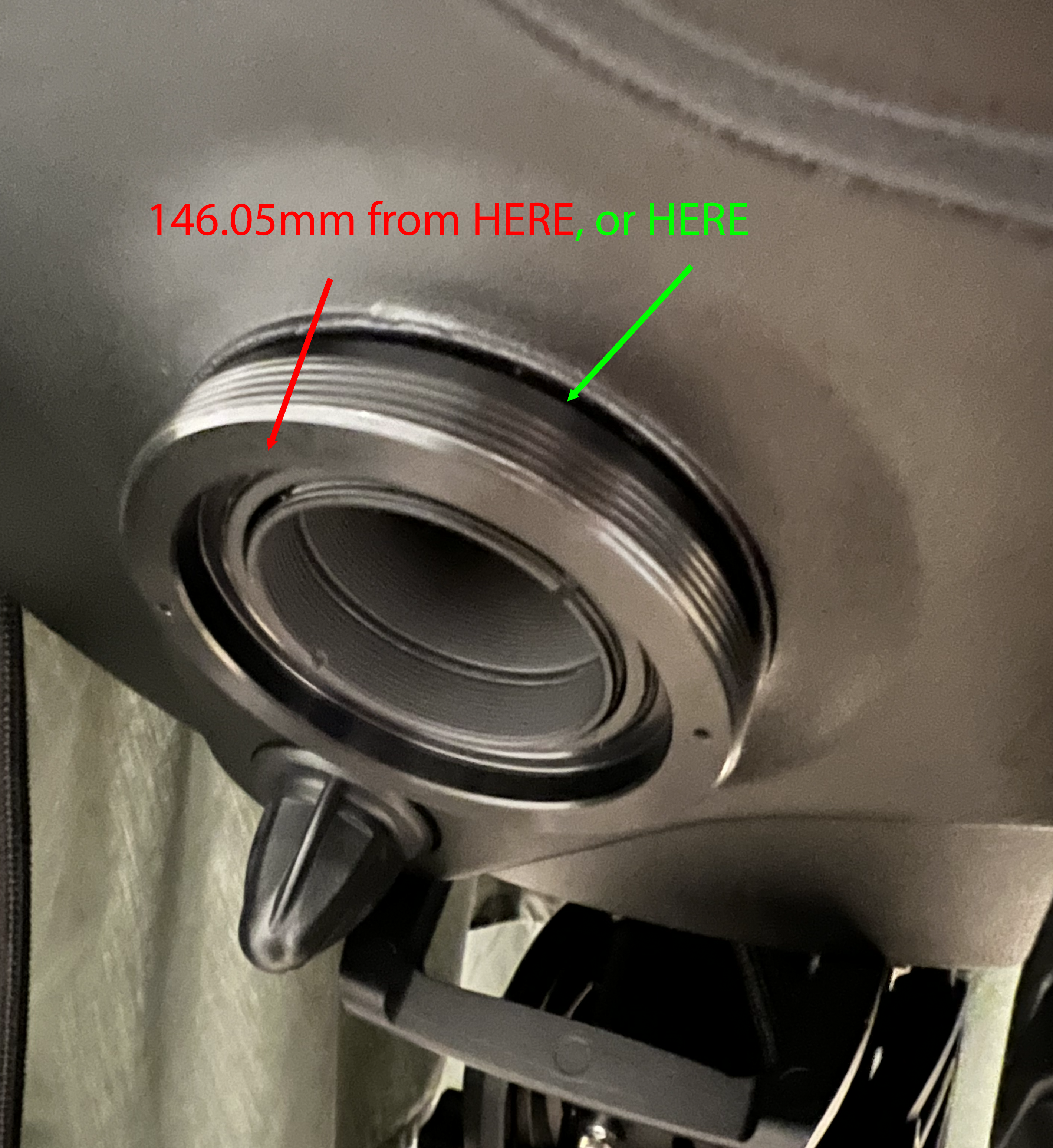
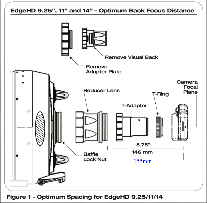
1) When you use a reducer (which I DO NOT advise), you first screw it into the rear of the scope as tight as it will go. Then you have to arrange spacers so that the sensor sits at 5.75" (146.05 mm) from the lip at the bottom of the threads. The lip has "0.7x Reducer Lens" printed on the edge. The reference surface is the edge just above the printing. If you are measuring from the rear of the threads as shown in the photo with the arrow, that is completely incorrect and you'll have some pretty noticeable field aberrations with a large sensor. The correct surface is show below. Hi @John Hayes, thank you so much again for your feedback, I really appreciate it. Are you sure it's from the lip and not the end of the threads (end towards the sensor) in the case of the reducer? The documentation on the reducer seems to indicate otherwise: 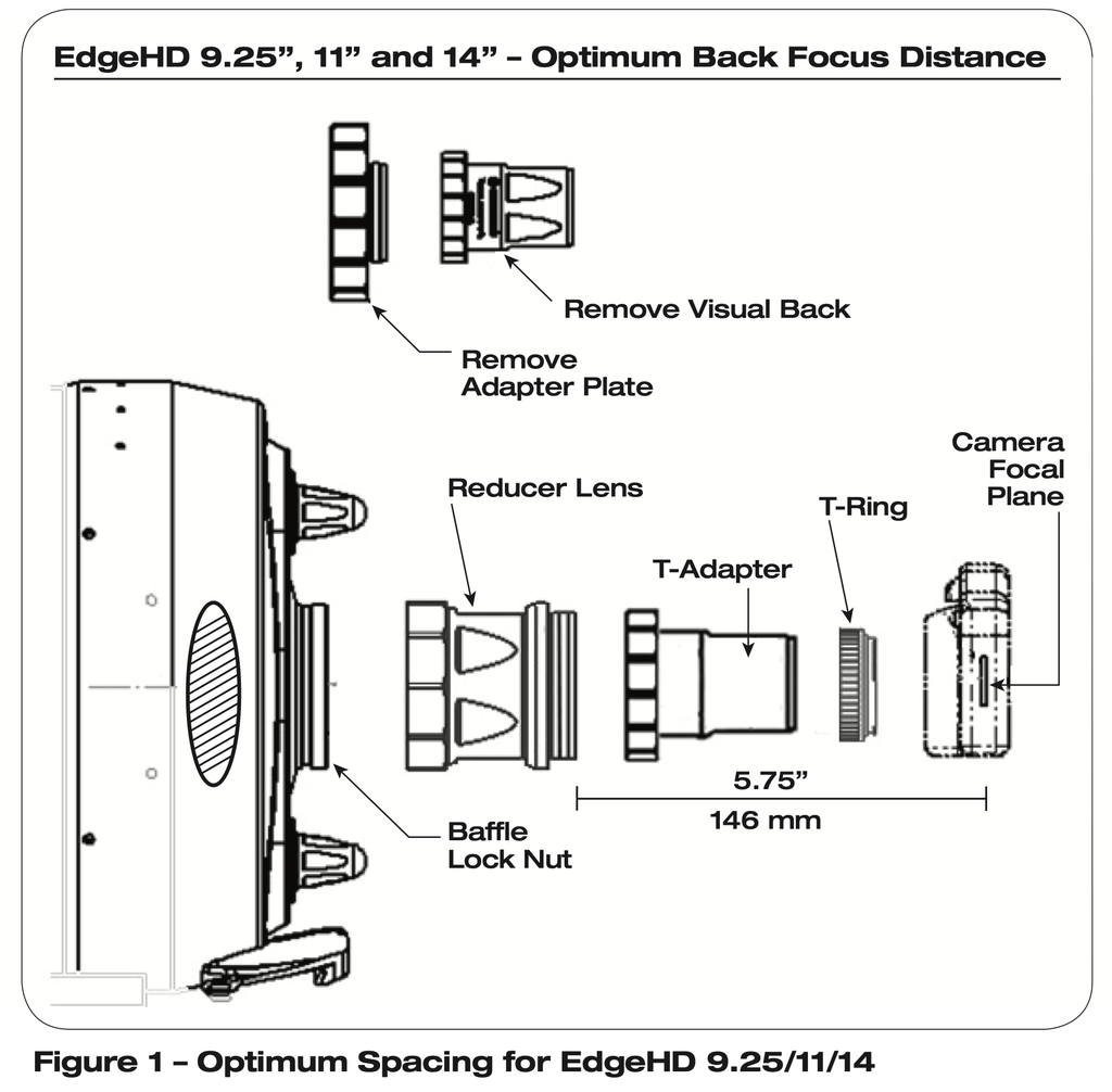 What about in the case of prime focus, F/10? Do you measure 146.05mm from the end of the threads (towards the sensor), or at the base of the threads closer to the scope (like above with the reducer at the lip)? It would be odd for one to be one way, and the other to be another way, particularly given that the thread for the F/7 reducer threads over the threading of the Baffle Lock Nut?  Regarding #3, about the Bahtinov mask, it's based on a zoomed in version. Numerous stars, over numerous nights, with an OSC Camera (ASI2600MC) and a Mono Camera (QHY268M across different Filters). Again, I appreciate your help.
|
You cannot like this item. Reason: "ANONYMOUS".
You cannot remove your like from this item.
Editing a post is only allowed within 24 hours after creating it.
You cannot Like this post because the topic is closed.
Copy the URL below to share a direct link to this post.
This post cannot be edited using the classic forums editor.
To edit this post, please enable the "New forums experience" in your settings.
"Are you sure it's from the lip and not the end of the threads (end towards the sensor) in the case of the reducer? The documentation on the reducer seems to indicate otherwise:"
I must be getting feeble minded. The reference surface on the scope itself is the rear of the baffle nut (shown in red above) so the reference surface on the reducer has to be the same surface that you originally referenced. I'm sorry for the error...and thanks for the dope slap! I'll modify my answer above so that we don't spread confusion.
John
|
You cannot like this item. Reason: "ANONYMOUS".
You cannot remove your like from this item.
Editing a post is only allowed within 24 hours after creating it.
You cannot Like this post because the topic is closed.
Copy the URL below to share a direct link to this post.
This post cannot be edited using the classic forums editor.
To edit this post, please enable the "New forums experience" in your settings.
@John Hayes Thanks so much for clarifying that, I appreciate it.
|
You cannot like this item. Reason: "ANONYMOUS".
You cannot remove your like from this item.
Editing a post is only allowed within 24 hours after creating it.
You cannot Like this post because the topic is closed.
Copy the URL below to share a direct link to this post.
This post cannot be edited using the classic forums editor.
To edit this post, please enable the "New forums experience" in your settings.
I found that focusing from the secondary mirror was a good solution. https://optecinc.com/astronomy/catalog/fastfocus/index.htm |
You cannot like this item. Reason: "ANONYMOUS".
You cannot remove your like from this item.
Editing a post is only allowed within 24 hours after creating it.
You cannot Like this post because the topic is closed.
Copy the URL below to share a direct link to this post.
This post cannot be edited using the classic forums editor.
To edit this post, please enable the "New forums experience" in your settings.
Thank you for the feedback, @Jim Matzger, I've been thinking about the Optec FastFocus as well.
|
You cannot like this item. Reason: "ANONYMOUS".
You cannot remove your like from this item.
Editing a post is only allowed within 24 hours after creating it.
You cannot Like this post because the topic is closed.
Copy the URL below to share a direct link to this post.
This post cannot be edited using the classic forums editor.
To edit this post, please enable the "New forums experience" in your settings.
I too have the 11" EDGE HD with Celstron .7 reducer. Using this diagram, I added 9 mm for the reducer threads and measured 155mm from the base of the reducer. You can't actually place calipers at the tip of the threads when everything is mounted, so one needs a visible target for the measurement. Why didn't Celestron take this into account in their documentation? Does that make sense? The thing is, I still think my stars could be tighter. I have seen other EDGE HD 11" and even non EDGE 11" images that have better looking stars than mine. My EDGE HD was recently cleaned and re-aligned to factory specs by Celestron. I shipped it to them and they did all of that. I am imaging in the Atacama Desert, with a 10 Micron GM 2000 and OAG-L with an ASI174 guide cam and an ASI2600MM Pro main cam. Given: Seeing, guiding and transparency will also affect star bloat. Seeing is 2" on average with better seeing more often than not. But for this reason I bin 2x. Guiding RMS is typically in the .5"/px range and when binned 2x my image scale is .8"/px. I seem to be looking for a way to definitively say my backfocus is corrrect. Would an adjustment of 1 or 2 mm one way or another actually be noticeable in the stars? For example, I did not account for the thickness of my filters.  |
You cannot like this item. Reason: "ANONYMOUS".
You cannot remove your like from this item.
Editing a post is only allowed within 24 hours after creating it.
You cannot Like this post because the topic is closed.
Copy the URL below to share a direct link to this post.
This post cannot be edited using the classic forums editor.
To edit this post, please enable the "New forums experience" in your settings.
Image quality in the field for the Edge 11 with a large sensor (24 mm x 36 mm) is sensitive to BWD spacing errors of about +/- 50 microns. If you want round stars in the corners, you'll need to account for the filter thickness and carefully dial in the correct spacing.
John
|
You cannot like this item. Reason: "ANONYMOUS".
You cannot remove your like from this item.
Editing a post is only allowed within 24 hours after creating it.
You cannot Like this post because the topic is closed.
Copy the URL below to share a direct link to this post.
This post cannot be edited using the classic forums editor.
To edit this post, please enable the "New forums experience" in your settings.
John Hayes:
Image quality in the field for the Edge 11 with a large sensor (24 mm x 36 mm) is sensitive to BWD spacing errors of about +/- 50 microns. If you want round stars in the corners, you'll need to account for the filter thickness and carefully dial in the correct spacing.
John thanks John, would it be a fair, succinct statement to say: If the stars in the corners are round, your back focus is correct?
|
You cannot like this item. Reason: "ANONYMOUS".
You cannot remove your like from this item.
Editing a post is only allowed within 24 hours after creating it.
You cannot Like this post because the topic is closed.
Copy the URL below to share a direct link to this post.
This post cannot be edited using the classic forums editor.
To edit this post, please enable the "New forums experience" in your settings.
Malcolm Park:
John Hayes:
Image quality in the field for the Edge 11 with a large sensor (24 mm x 36 mm) is sensitive to BWD spacing errors of about +/- 50 microns. If you want round stars in the corners, you'll need to account for the filter thickness and carefully dial in the correct spacing.
John
thanks John, would it be a fair, succinct statement to say: If the stars in the corners are round, your back focus is correct? If your stars are are both small and round over the entire field, then you are good to go. John
|
You cannot like this item. Reason: "ANONYMOUS".
You cannot remove your like from this item.
Editing a post is only allowed within 24 hours after creating it.
You cannot Like this post because the topic is closed.
Copy the URL below to share a direct link to this post.
This post cannot be edited using the classic forums editor.
To edit this post, please enable the "New forums experience" in your settings.
John Hayes:
Malcolm Park:
John Hayes:
Image quality in the field for the Edge 11 with a large sensor (24 mm x 36 mm) is sensitive to BWD spacing errors of about +/- 50 microns. If you want round stars in the corners, you'll need to account for the filter thickness and carefully dial in the correct spacing.
John
thanks John, would it be a fair, succinct statement to say: If the stars in the corners are round, your back focus is correct?
If your stars are are both small and round over the entire field, then you are good to go.
John
==========================================================================
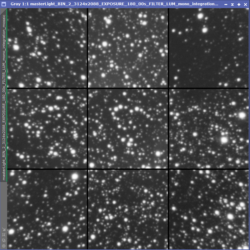
Needs work 
 |
You cannot like this item. Reason: "ANONYMOUS".
You cannot remove your like from this item.
Editing a post is only allowed within 24 hours after creating it.
You cannot Like this post because the topic is closed.
Copy the URL below to share a direct link to this post.
This post cannot be edited using the classic forums editor.
To edit this post, please enable the "New forums experience" in your settings.
It's not absolutely perfect, but I'd sure call that close enough! So… it looks to me like you are good to go.
John
|
You cannot like this item. Reason: "ANONYMOUS".
You cannot remove your like from this item.
Editing a post is only allowed within 24 hours after creating it.
You cannot Like this post because the topic is closed.
Copy the URL below to share a direct link to this post.
This post cannot be edited using the classic forums editor.
To edit this post, please enable the "New forums experience" in your settings.