I have been enjoying various telescopes for 26 years. My first telescope was a Soligor brand Newton that I still have. I learned to collimate this Newton when laser collimators, computer programs, digital cameras, tribahthinov masks or special Knobs did not exist and it has never taken more than 5 minutes to get it perfect.
A few years ago I acquired a celestron C8 EDGE, a wonderful telescope but with complicated collimation, especially for beginners.
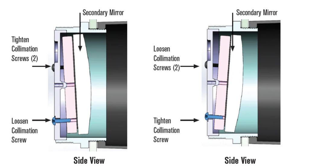
When I started collimating the C8 I noticed a big difference compared to the Newton. The screws were looser, they did not feel firm and most importantly on the C8 when I tightened a screw and loosened it again or did not notice the mirror return to its initial position, which forced me a multitude of extra corrections compared to the Newton .
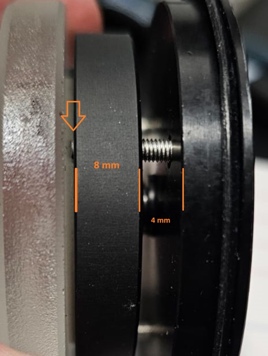
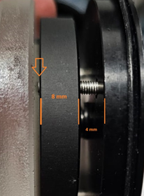
I disassembled both secondary mirrors, to see the differences. I attach photos.
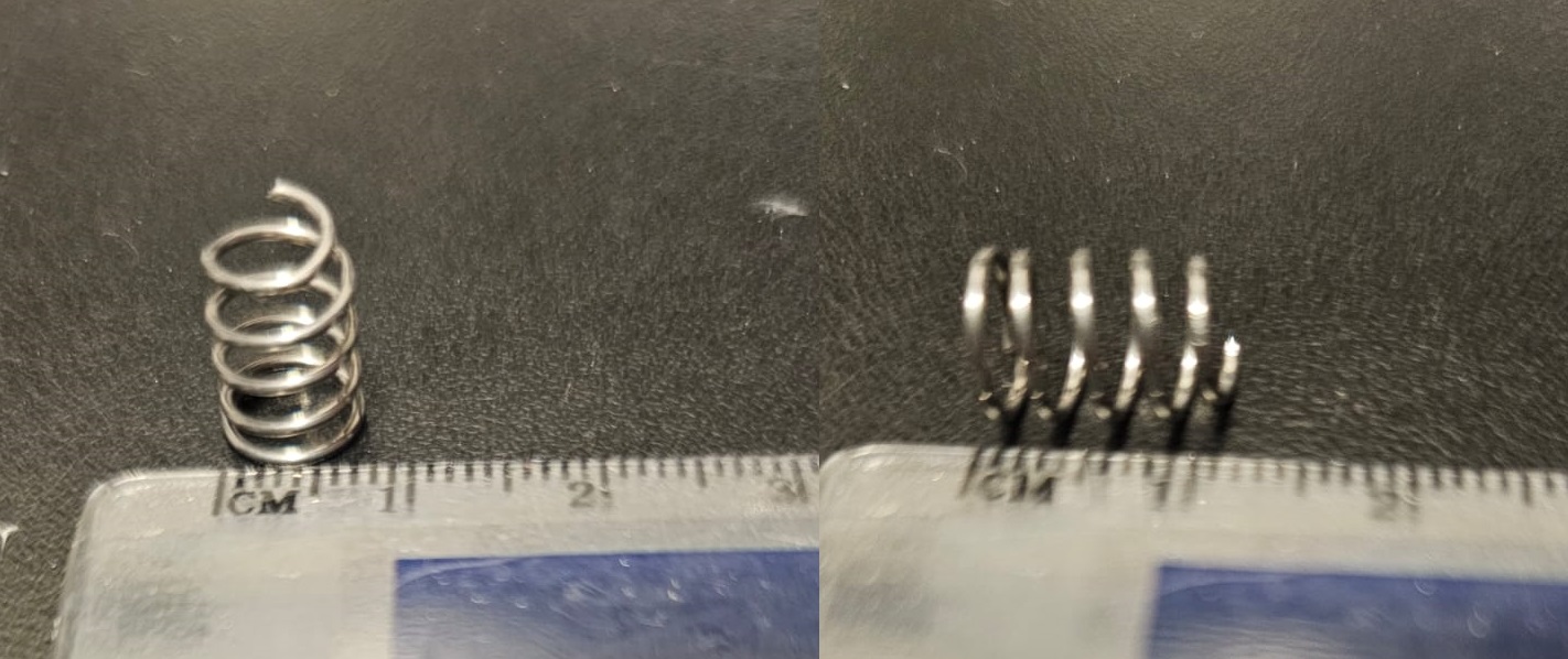
Newton:
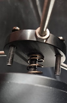
Celestron C8 EDGE. No tension.
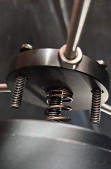
The two huge differences are, firstly, that the Newton has a spring that tensions the secondary mirror and secondly, the mirror is held by a tilting screw.This has enormous advantages. The first, when under tension the screws are firmer and greater control is obtained when tightening and loosening. The second and most important, when a screw is loosened, the spring pushes the mirror, so we have total control without the need to adjust other screws. Finally, the presence of the tilting screw prevents accidents, since if it were not there, as happens in the Celestron C8, if we loosen the 3 screws too much the secondary mirror would fall on the primary one.
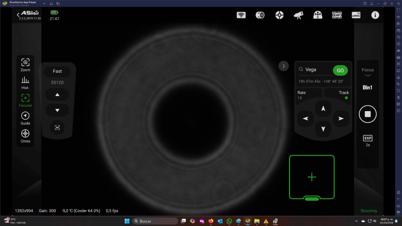
To obtain the advantages of the secondary mirror that appears in many Newton telescopes, I propose two improvements that are very economical.
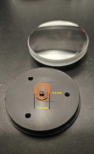
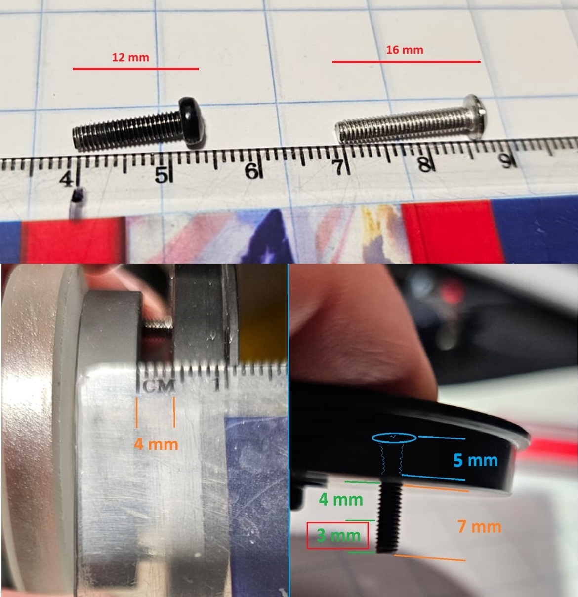
The first is to place a spring 7 to 10 mm wide by 5 mm high on the axis with a blunt tip where the mirror tilts. It is an easy spring to acquire and find in a multitude of components that we have at home. With this we will have the tension that will help us in collimation. The second improvement is to change the screws for about 10 mm longer, which provides greater security.

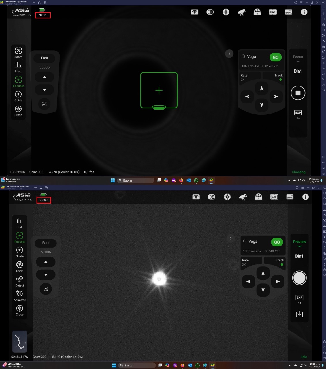
Sometimes when the collimation is achieved, the screws are not firmly secured, so they decollimate when changing position. It is not for nothing that many users collimate with Jupiter's moons before pointing at Jupiter, so as not to move the telescope too much. This problem is eliminated with spring tension.
I have made these improvements and I can calibrate perfectly in less than 10 minutes, without stress, without problems. When I collimated without the central spring I spent 2 hours on it and never obtained the desired collimation. Of course experience helps and celestron owners acquire skill and achieve perfect collimations in minutes, even more so with the new accessories that are available to help.
I hope that helps.